Sunday, April 3, 2022

Gear Hobbing Machine: Everything You need to Know about Gear Hobbing


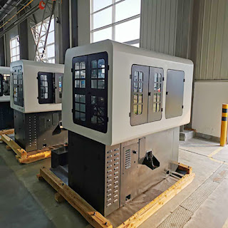
Gear Hobbing Machine


Gear hobbing has been an integral part of gear making. Whereas milling would be used to produce the basic gear shape, gear hobbing performs the much more intricate task of shaping the gear. Various facets of gear teeth emerge once hobbing is complete, including its thickness, profile and addendum.

Gear hobbing is a specialised process of gear cutting, spline cutting and sprocket cutting. The central equipment in the gear hobbing process is the milling machine. This gear hobbing machine does the task of cutting the spline or teeth using a series of cuts using a hob. Gear hobbing is often used for spur gear and helical gear making, because of its ease of use and cost effectiveness.


Construction Of Gear Hobbing Machine

Hob– In this process, the gear blank is rolled with a rotating cutter called a hob. Gear hobbing is done by using a multipoint cutting tool called gear hob. It looks like a worm gear having a number of straight flutes all around its periphery parallel to its axis. These flutes are so shaped by giving proper angles to them so that these work as cutting edges.

In gear hobbing operation, the hob is rotated at a suitable rpm and simultaneously fed to the gear blank.

The gear blank is also kept as revolving. Rpm of both, gear blank and gear hob are so synchronized that for each revolution of gear bob the gear blank rotates by a distance equal to one pitch distance of the gear to be cut.

The motion of both gear blank and hob is maintained continuously and steady. A gear hob is shown in Figure and the process of gear hobbing is illustrated in Figure

The hob teeth behave like screw threads, having a definite helix angle. During operation the hob is tilted to helix angle so that its cutting edges remain square with the gear blank.

Gear hobbing is used for making a wide variety of gears like spur gear, helical, hearing-bone, splines and gear sprockets, etc.


Types Of Hobbing Process :

The process of gear hobbing is classified into different types according to the directions of feeding the hob for gear cutting. The classification is described as given below.

• Hobbing with Axial Feed

In this process the gear hob is fed against the gear blank along the face of the blank and parallel to its axis. This is used to make spur and helical gears.

• Hobbing with Radial Feed

In this method the hob and gear blanks are set with their axis normal to each other. The rotating hob is fed against the gear blank in radial direction or perpendicular to the axis of gear blank. This method is used to make the worm wheels.

• Hobbing with Tangential Feed

This is also used for cutting teeth on the worm wheel. In this case, the hob is held with its axis horizontal but at the right angle to the axis of the blank. The hob is set at full depth of the tooth and then fed forward axially. The hob is fed tangentially to the face of the gear blank.


Gear Hobbing Machine


The process of gear hobbing is as follows:

• The gear hobbing machine is checked for any mechanical issues. This includes the synchronisation of the rotating gears for the workpiece and the hob.

• The gear hobbing machine has two skew spindles, one of which has the gear blank while the other one has the hob.

• The spindles are set at an angle from each other, depending on the type of teeth to be set on the gear blank.

• The two spindle shafts are then rotated proportionally with the hob cuts on the gear blank. Having them properly rotating is the key to making the right gear teeth on the gear blank.

• The hob would then be applied to the gear blank until the correct tooth depth has been reached.

• The hob is then run through the gear blank’s axis of rotation as a final step.

• The process is repeated for each gear blank, which is often stacked one atop another. The rotation ensures identical gear spindle depth and a consistent number of teeth on each gear blank.

• The completed gears are removed from the milling machine.

• The central tool to gear hobbing is the hob, a worm-shaped cutter. The hob makes successive cuts on the gear blank to create the gear teeth. In order for the cutting to be precise, the gear blank and the hob must be synchronised in the rotation.


The 5 Advantages of Gear Hobbing

Gear manufacturing gives us lots of options. There are a handful of different processes we can use to make dozens of different gear types from dozens of different materials. Accordingly, when we choose a gear manufacturing method, it’s because it’s the best one for the job.

Gear hobbing is just one way we can manufacture gears. It relies on a special form milling machine with a tool known as a hob, which generates the teeth in both gears and splines. So what are the advantages of this process?

• Speed. Some gear manufacturing processes take a long time, but gear hobbing is relatively fast. The machine is simple, so it doesn’t require as much operational attention, and for some gears, we can stack multiple units to hob them all at the same time.

• Precision. That said, not just anyone can operate a hobbing machine. With the right expertise, hobbing can be highly precise, resulting in high quality gears.

• Flexibility. There’s more than one type of hob—and more than one type of hobbing machine. There are countless variations that cater to specialized applications, so you always have options available.

• Applications. While hobbing is often used for spur gears, the process can be used for a variety of other gears, such as cycloid gears, helical gears, worm gears, ratchets, splines, and sprockets (as long as you have the right tools for the job).

• Related processes. One of hobbing’s only weaknesses is that it does not work for internal gears (with inward-facing teeth). However, there’s a related process called shaping that can be used instead—with all the same advantages of hobbing.


Geepro Machinery

WUXI GEEPRO GEAR HOBBING MACHINE has been one of the professional gear hobbing machine manufacturer and supplier in China since 2007.

Benefits From Our Advantages:

• Professtional Sales Engineers

• Stable Performance of Machines

• Reasonable Price For Users

• Long Life After-Sales Service

We provide high speed high accuracy gear machinery and other workpieces solutions with premium quality service to global users. Contact us now!

Wednesday, March 30, 2022

What is the method to maintain the centering machine tool?

End milling and centering machine tool is a kind of processing machine, also called milling machine. It has high efficiency, high consistency and high precision. It can complete the processing of two positioning end faces and center holes of various shaft parts. It provides high-efficiency and high-precision positioning benchmarks for all subsequent tasks. In the production of high-efficiency shaft parts, the role of milling face centering machine tools is becoming more and more important, which is closely related to the processing of the positioning reference of shaft parts. It can be said that one of the important indicators that affect the production and processing efficiency of the entire shaft part is the milling end face centering machine tool. It is an ideal and necessary for processing automobile half shafts, camshafts, crankshafts, gearbox shafts and motor shafts. Indispensable processing equipment.

The CNC milling and centering machine tool adopts horizontal CNC servo drive mode. The power heads at both ends simultaneously complete the milling of both ends of the workpiece, and the other end simultaneously completes the drilling of the center holes or outer circles at both ends. It has rigidity. Excellent, high precision, strong flexibility, stable work, high processing efficiency.


The method of maintenance of the milling machine

1. Check the liquid level of the cooling oil tank and water tank at any time and add oil or water in time. If it is too dirty, you need to replace or clean the oil tank, water tank and filter

2. Check the waste oil pool frequently and remove the accumulated waste oil to avoid overflow.

3. Frequently clean the paper cutter and check for paper jams, etc.

4. Check the shaft drive belt from time to time, and adjust the tightness of the belt according to the instructions.

5. From time to time, press the insert on the guide rail on the roller, and adjust the tightness according to the instructions.


What is the method to maintain the centering machine tool?

Monday, March 21, 2022

What is the use of plastic pipe threading machine?

Plastic pipe threading machine is used for threading the plastic pipe ports of plastic (PE pipe, PVC pipe) and other materials. This machine has the characteristics of high precision, uniform threading and fast speed. It is a plastic pipe sleeve for construction sites, factories and other related industries. Ideal product for buckle.Plastic pipe threading machines have various types of plastic pipe threading machines with a diameter of 10mm-3300mm, which are suitable for processing plastic pipe threads of various industries and materials.

It can be widely used in mining gas pipe threading machine, PVC drilling pipe threading machine, PVC drilling pipe threading machine, plastic pipe threading machine for geological exploration, special threading machine for fire extinguisher siphon pipe, PVC pipe, PE pipe and PP pipe A series of plastic pipe internal and external thread processing equipment such as screw machine, and various special-shaped plastic pipe thread processing machines can also be customized.

What is the use of plastic pipe threading machine?

Wuxi Geepro Machinery Import & Export Co., Ltd. has been focusing on Gear Machinery since 2007 and is one of the most professional CNC Gear Hobbing Machine Manufacturers In China, export CNC Gear Hobbing Machine, Honing Tools. If you are interested in our products, please click here to visit our website and be happy to become a partner.

Sunday, March 13, 2022

The determination of machining technology of parts by CNC spline milling

CNC spline milling is mainly used to process different product components such as spline shafts and gears. The structure design is reasonable and the machining accuracy is stable. It is mainly driven by spiral arc bevel gears. The headbox worm adopts independent lubrication. Each processing part adopts high-quality cast iron and adopts advanced treatment, and the processing performance is stable.

CNC spline milling is a special machine tool that uses the hobbing method to process straight groove spline uranium and gears with small teeth. It is suitable for the processing of spline uranium and gear shafts in the automobile, tractor industry, machine tool manufacturing, hydraulic manufacturing, lifting machinery, construction machinery and other industries.

Determination of the machining process of CNC spline milling parts:

1. Part process analysis

The process analysis of this part is mainly carried out from the aspects of structure shape, size and technical requirements, positioning foundation and blank. The part has a complex shape and is an axisymmetric figure. The dimensions of the part must be reasonably marked, the axial dimension accuracy is high, and the surface roughness must be rough and finished, and then processed on a grinder. The part has a spline that needs to be heat treated.

2. Determine the blank

Due to the complex shape and structure of the parts, if the bar is directly processed, the cutting performance of the parts can not be guaranteed and it is not economical. Therefore, the use of die forging to make the blank can save time and labor, and can also improve the cutting performance of the parts.

3. Processing method

According to the machining surface of the part (external circle, end face, key, keyway and threaded hole), part material and tolerance level and surface roughness requirements, consult the part surface processing method, processing economic accuracy and surface roughness related content in the process manual, and its processing Methods as below:

a. External surface

The surface roughness is Ra0.8μm, and rough turning, semi-finishing turning, rough grinding and fine grinding are required.

b. End face

The end face of the part is the end face of the revolving body, and the dimensional accuracy is not high. The surface roughness is Ra1.6μm and Ra12.5μm. The end face of Ra1.6μm can be rough turning, semi-finishing and rough grinding, and the end face of Ra12.5μm can be roughed to meet the requirements.

c. Slot

The tolerance level of groove width and groove depth is IT8, and a three-face milling cutter is required for rough milling and semi-finish milling.

d. Threaded hole

According to GB regulations, its tolerance class is IT14, and drilling is required.


WUXI GEEPRO GEAR HOBBING MACHINE has been one of the professional CNC spline milling manufacturer and supplier in China since 2007.OEM service is also available.Feel free to contact us with your need or questions.


The determination of machining technology of parts by CNC spline milling

Saturday, March 5, 2022

A Short History of Gears


Gear Cutting Machine


Gears are considered as one of the oldest equipment known to mankind. The origin of gears goes down to the Chinese South-Pointing Chariot in the 27th Century B.C. This chariot was known to pointing to the south no matter how it was turned.

Aristotle has the credit to his name of giving the earliest description of gears in the 4th century B.C. According to his definition, the direction of rotation is reversed when one ear wheel drives another gear wheel. Gears have been used by the Greek Inventors in water wheels and clocks. The sketches of various types of gears of this time can be found in the notebooks of Leonardo da Vinci.

Even after these ground-breaking discoveries, no major development concerning wheels was made until the 17th Century. In this time, first attempts were made to provide constant velocity ratios. These attempts utilized the involute curves. This was just the beginning of something that changed the world for all the good reasons. However, in the 19th century, form cutters and rotating cutters were first used and it was then in 1835 when the English inventor Whitworth patented the first gear hobbing process.

Various other patents followed until 1897 when Herman Pfauter of Germany invented the first hobbing machine capable of cutting both spur and helical gears. Through the 20th century, various types of machines developed. But, the next major step came in 1975 when the Pfauter Company in Germany introduced the first NC hobbing machine and in 1982 the Full 6 axis machine was introduced.


Today

Gears or Cogs are in just about everything containing a spinning part, that is, from cars to clocks. Car's transmissions and engines contain lots of cogs that help in reducing the gear in motorized equipment. There're other lots of important jobs performed by these simple machines.

Besides being used in the industry, gears are also being used in different toys and they are one of the major components in toy cars and other toys to help them move. Even in smaller toys, gears are used in different sizes to ensure the proper functionality of them.

Gear manufacturers primarily use CNC machines to cut gears from blanks, and our level of precision is driven by sophisticated design software and advanced engineering theories. Modern gears are exceptional pieces of work, capable of lasting centuries (or longer, if cared for properly), and technology continues to advance to bring us better ways of producing gears.


If you have a custom made gear to order, or need a quote for a large project, be sure to contact us today!

Friday, February 25, 2022

YK2212B CNC Spiral Bevel Gear Cutting Machine

CNC Gear Cutting Machine   CNC Gear Cutting Machine Manufacturers


PRODUCT DESCRIPTION

YK2212B YKT2250 YK2312 YK2712 CNC spiral bevel gear cutting generator machine Features:

The machine is designed to operate as a three-axes CNC control Spiral Bevel Gear Generator, i.e. cradle oscillation(X axis), work spindle rotation(Y axis) and sliding base movement(Z axis)being simultaneously controlled by the CNC control system to cut gears.

The rotation of cutter spindle is controlled by . frequency-variable motor for its stepless control. There are no any change gears on the machine for easy operation, variety application and minimizing the setting time of machine. The machine settings calculated for YT2250 machine can be converted into the relative machine sttings of YKT2250 machine.

When setting the cutter by hand, the power of main motor will be off, so as to protect the operation. Three axes (X, Y and Z) will be back to zero positions through switches for ensuring the high accuracy and there are forward and backward limit switches for Z axis.

A high precision worm gear set is used for cradle drive and work spindle drive respectively, which are controlled by AC servo system for getting high machining accuracy, the machine is with higher structural and driving rigidities.

The machine is equipped with CNC Control System 802D(SIEMENS), AC digital servo system and frequency variable regulator to accomplish the automatic or manual control and fault detecting.

The machine is equipped with an independent sealed electrical cabinet, which is with air conditioner or thermo exchanger.

Safety guards and auto-chip conveyor can be provided on the machine


Specifications

Unit

Parameter

Max. modulus

mm

10

Max. pitch cone distance (Spiral angle 300)

mm

260

Max. pitch diameter (Spiral angle 30, ratio 10:1)

mm

500


Root angle


Max. 90°

Min. 5°

Max. ratio (shaft angle 90°)


10:1

Max. spiral angle


50°

Max. cutter depth

mm

20

Max. face width

mm

70

Max. number of teeth


5~100

Diameter of taper hole at large en

mm

100

Taper


1:20

Length of taper

mm

160


https://www.geeprohobbing.com/gear-cutting-machine.html

Wednesday, February 16, 2022

HM-KL915 CNC Honing Machine with Finishes of 0.1-0.2 um


                                                     CNC Honing Machine Manufacturer


PRODUCT DESCRIPTION

HM-KL915 CNC Honing Machine

Max Honing Diameter: Ø12--Ø200mm

Max Honing Depth: 600mm


Main Specification:

1

Machining Hole Diameter

Ø12-Ø200mm

2

Allowable load of table

200kg

3

Maximum stroke Depth

600mm

4

Spindle motor power

1.5KW

5

Spindle reducer ratio

3:1

6

Spindle Speed range

100-1000rpm(CVT)

7

Return Oil Pump flow

100L/min

8

Stroke Motor

2.2KW

9

Stroke Control Type

“Servo Motor+Ball Screw”

10

Stroke Speed

0-40m/min(CVT)

11

Honing tool Qty

1 Axis

12

Single Working Station

1(Single Honing tool)

13

Feeding Torque

≥20NM

14

Honing Accuracy

≤0.1mm

15

Feeding Type

Constant feed

16

Machine Weight

About 2.5 Tons

17

Machine Size L×W×H

1500×1500×2700mm

18

Noise standard

Less 80 dB Normally


Wuxi Geepro Machinery Import & Export Co., Ltd. has been focusing on Gear Machinery since 2007 and is one of the most professional CNC Gear Hobbing Machine Manufacturers In China, export CNC Gear Hobbing Machine, Honing Tools. If you are interested in our products, please click here to visit our website and be happy to become a partner.


https://www.geeprohobbing.com/products/hm-kl915-cnc-honing-machine.html

What is the honing process? Machine honing explained

  Honing or Grinding? Choosing the Right Finishing Process for Your Needs in Modern Manufacturing Honing and grinding are both abrasive mach...